Motorized roof
No self-respecting astronomical observatory can function without an opening roof. Blueberry uses a sliding roof mechanism known as a ‘roll-off’. As a result of analyses, it was decided to discard the idea of installing a dome due to its significant disadvantage, which is the the inability to use more than one telescope. In addition, the circular design makes it difficult to efficiently place additional equipment such as a desk or a cabinet.
Humble beginning
The weight of the roof is estimated to total between 600 and 650 kg. It is seated on six carriages running on steel rails, which minimises rolling resistance. Nevertheless, manually moving the of the roof by an adult poses some challenges, especially as it is necessary to apply force at a height of approximately 180 cm above the floor, which is 50 cm above ground level. That was the drive version 1.
The concept of two ropes, attached to opposing girders (the horizontal beams on which the the roof rests on). For greater convenience, the cables could be wrapped around a short handle, which gave a much better grip. Soon there were several loops along the rope, making it possible to mount the handle in several places, depending on the degree of roof position. The ropes performed much better, but were not without their drawbacks. They dangled and there was a risk that they could get entangled around the telescope or any of the fittings. They also had another fundamental disadvantage in common with the previous concept - they required presence on site, with no chance of of automation. The v2 drive was some progress, but ultimately proved to be a dead end.
Electric drive
There are several solutions on the market dedicated to observatories, but none of them met my specific requirements. The main problem was the size of the observatory in Borówka, at over 5 by 5 metres, and the the associated weight of the roof. As a result, I took the decision to design the system from scratch. In this process, I received invaluable help I received from Wojtek and Kamil, owners of two nearby observatories, for which I would like to thank them sincerely.
Motor and roof load
The v3 main drive is a motor for sliding gates - the BTF Icaro Ultra AC A2000. It is capable of moving gates weighing up to 2000 kg. This seems like a lot, but the matter is not as obvious as it might seem. The gates are are usually placed on two or three bogies and are not supported along their entire length for a large part of their range of movement. The entire weight is distributed in a single line. In the case of the roof, it is supported at all times by 6 bogies that move on two rails. The roof has no counterweights. However, it has another problem - potential snow.
The roof also has to work in winter, after a snowfall. Cold winter nights often offer great viewing conditions. This is why it is so important that the roof is also operational when covered with snow. The roof area is approximately 40 m2 . The weight of the snow is strongly dependent on its nature. A snowdrift weighs about 200kg per m3. A snowfall of 50 cm is is rather rare, but it is not completely out of the question. Assuming that 50cm of snow would fall, there would be 100kg of snow on each m2 and about 4 tonnes on the entire roof.
Estimating the weight of the roof itself is rather coarse. The two biggest unknowns are the weight and volume of the timber. The roof The roof is supported on 4 beams, with a profile of 14x14cm and a length of 5m or 5.25m. Here the estimation is quite precise, although the hewing has reduced the volume somewhat. The roof has 8 bays, each consisting of diagonal elements cut at unusual angles, projecting beyond the contour of the building, etc. The unit weight of the roof sheeting is well known, while the the width of the overlaps is unknown. The mass of the flashing, i.e. the finishing elements of the the edge of the roof. The elements that were able to be estimated came out to 611kg, so I can assume that the additional elements I can therefore assume that the additional elements not included in the estimate increased the total weight to 650kg.
The roof is supported on 6 bogies with a capacity of 2500kg each, so the bogies alone can carry a load of up to 15 tonnes. The building’s superstructure consists of 16 14x14cm columns. It appears that the structure is robust enough that it should easily withstand the load even in the biggest snowstorms.
The fitted BFT Icaro Ultra motor is designed for gates weighing up to 2000kg. However, this value is somewhat misleading, as the same motor in the veloce version offers faster movement for gates up to 1000kg. They differ only by the size of the sprocket. In the case of the observatory, I used an 18:25 gear ratio, so from a simple proportion shows that the motor should be able to cope with a weight of up to 2778kg. Another important factor, which unfortunately I can’t estimate is the different design. The gates usually move on two or three bogies, the weight is distributed along a single line. The bogies are mounted statically and the sliding gate has counterweights, which prevent it from being reset in positions where the end of the door is not supported. The roof is supported on 6 bogies that are in full contact with the rails at all times. I think the additional evenly distributed support improves rolling resistance. Will it work after a snowstorm that brings half a metre of snow? There is only one way to find out: wait and see.
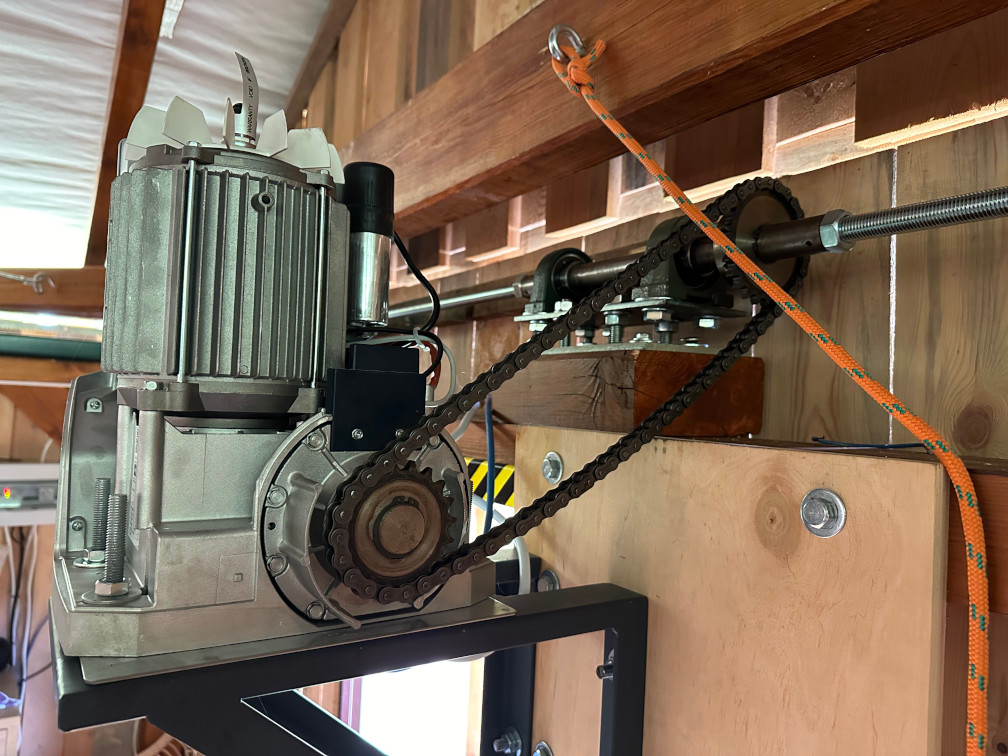
The engine with the housing removed and the chain on looks like this:
Drive shaft
Wojtek and Marceli, the owners of the friendly observatory, initially made the drive in such a way that the transmission was only done along one of the two rails. This drive design is simpler. You can fit the motor from the gate with virtually no modifications. Unfortunately, over time, the unfortunate unfortunate consequences of this solution. The forces acting on only one side caused the roof to twist (‘skew’) of the roof. With the inevitable formation of play, the roof increasingly took on a rhomboid shape during movement. rhomboidal shape. Worse still, each time the roof was closed and opened, it deformed in opposite directions, which only compounded the degradation of its rigidity. Even Kamil and Michał, from the Astrobudka observatory, came to similar conclusions, although in their case the initial drive was slightly different (a toothed bar passing through the centre of the roof).
In all three observatories, the conclusion is the same: in roofs of this size, the drive transmission must be from two sides. This is also how the drive in Borówka was designed. The central drive element is the gantry motor. Its gantry sprocket has been replaced by a Z18 chain sprocket, which transmits the drive via an 08B-1 chain to another Z25 sprocket, mounted on the shaft.
The total length of the shaft is 489cm. It is not practical to roll out such a shaft in one piece. Perhaps somehow possible, but machining and transporting a piece of this size would complicate and increase the cost of the operations. The shaft therefore consists of 5 main components:
- end shaft - terminated by a drive pinion, which transmits the drive to the toothed bar
- threaded rod fi 20
- central shaft - connects the two rods and has a chain sprocket, which transfers the drive from the motor to the shaft
- threaded rod fi 20
- end shaft
The design of the central shaft looks like this:

This approach has another huge advantage. The threaded rods can easily be cut on site to the correct length, and if you make a mistake, it will take an hour to buy a new bar. In the event of trying to turn such a component from scratch, the costs and delays would be orders of magnitude greater.
However, this technology has some limitations. In 2024 Poland, I have not been able to find a wholesaler that sells threaded rods longer than 2 metres.
And this is how the made and mounted central shaft looks like:
The only difference between the design and the execution is the change from external to internal threads. The change was suggested by turner. The internal thread is more robust, and it also simplifies the construction, as there were no need for couplings and counterblocks.
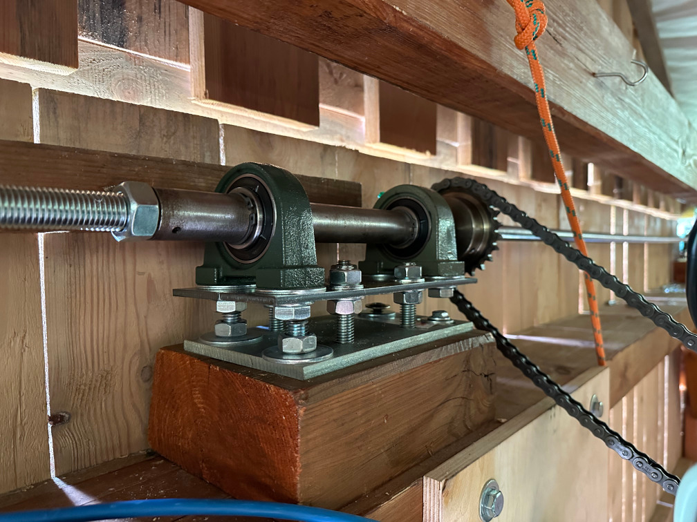
Both end shafts are identical. Each of the three shafts is mounted on two UCPA-206 bearings. The shafts have grooves in which Seger rings are fitted. These clever spring rings can be stretched slightly, and once in place, they hold firmly in place and prevent the entire shaft from moving. Rings Seger rings have standardised sizes. For a fi 30mm shaft, a Z30 ring is purchased. The actual diameter is smaller.
The plan of the end shaft is as follows: 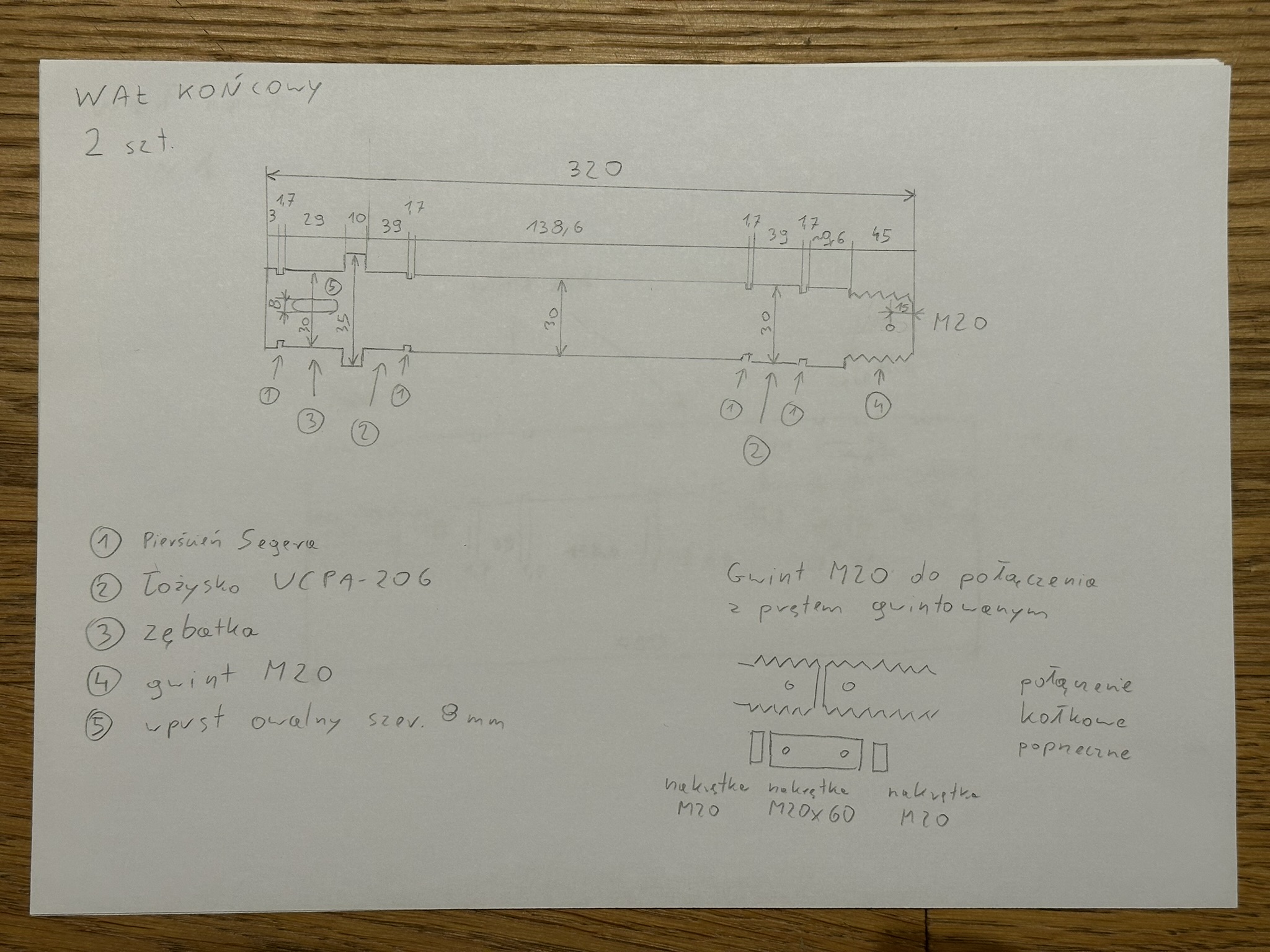
The shafts are secured with counter-nuts and spring pins placed across. Drilling a hole in M88 steel threaded rod was quite a challenge. The best DeWalt extreme cobalt drill bits were dulling after several drillings.
And this is what the end shaft looks like assembled and set in place: 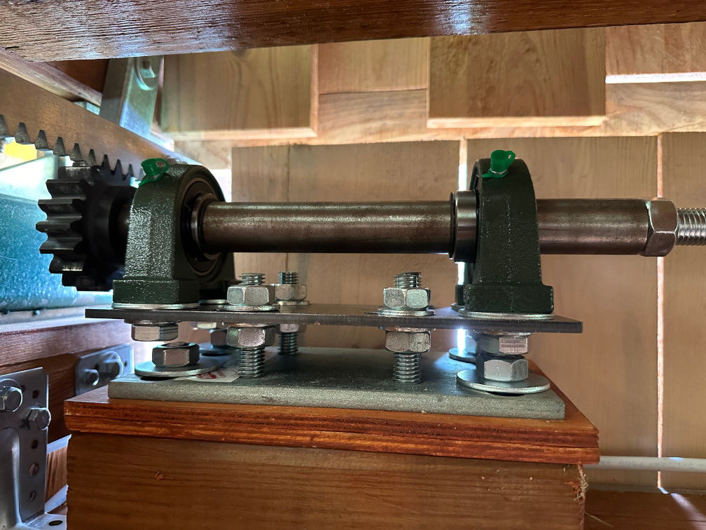
The first attempts to make the design in FreeCAD were unsuccessful. Although it is powerful, less advanced users are put off by its confusing interface, the multitude of modes and the large number of errors that are difficult to difficult to diagnose errors. Although I drew the entire skeleton of the observatory in FreeCAD, the design of the shafts I made the design of the rollers using the classic method - pencil on paper. Sometimes a bit of the traditional method doesn’t hurt.
The rollers were CNC milled by Krzysztof from 3D Carbon shop in Chwaszczyno, whom I highly recommend.
Shaft adjustment
In order to position the entire shaft accurately, each shaft is seated on two formers. Each has longitudinal holes, known as ‘bean holes’, which allow adjustment in one axis - one format longitudinally and the other across the shaft. The whole is supported by screws that allow adjustment in a third axis. In this way it was possible to set the shaft alignment exactly. I was afraid that a slightly crooked shaft would, over time bend and the pinions would wear on one side.
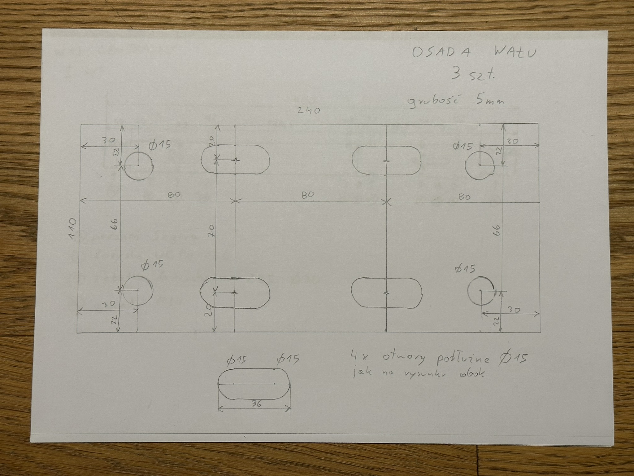
The shaft axle design looks like this:
Summary
I am a programmer and am not familiar with bearing types, gears, gantry motors, control automation, locksmith and lathe problems and much more. The subject has consumed a huge amount of time. Well over a hundred hours and almost half a year. But I finally got it over with. The drive works. The roof pushes back with the push of a button. The next step was automation, but I will devote a separate entry to that soon.
